Gamma Camera
Reference : http://www.physics.ubc.ca/~mirg/home/tutorial/hardware.html

Once a radiopharmaceutical has been administered, it is necessary to detect the gamma ray emissions in order to attain the functional information. The instrument used in Nuclear Medicine for the detection of gamma rays is known as the Gamma camera. The components making up the gamma camera are the collimator, detector crystal, photomultiplier tube array, position logic circuits, and the data analysis computer. The purpose of each is briefly described below.
 .
.
- Camera Collimator.
- Scintillation Detector.
- Photomultiplier Tubes.
- Position Circuitry.
- Data Analysis Computer
1. Camera Collimator
The first object that an emitted gamma photon encounters after exiting the body is the collimator. The collimator is a pattern of holes through gamma ray absorbing material, usually lead or tungsten, that allows the projection of the gamma ray image onto the detector crystal. The collimator achieves this by only allowing those gamma rays traveling along certain directions to reach the detector; this ensures that the position on the detector accurately depicts the originating location of the gamma ray.

2. Scintillation DetectorIn order to detect the gamma photon we use scintillation detectors. A Thallium-activated Sodium Iodide [NaI(Tl)] detector crystal is generally used in Gamma cameras. This is due to this crystal’s optimal detection efficiency for the gamma ray energies of radionuclide emission common to Nuclear Medicine. A detector crystal may be circular or rectangular. It is typically 3/8″ thick and has dimensions of 30-50 cm. A gamma ray photon interacts with the detector by means of the Photoelectric Effect or Compton Scattering with the iodide ions of the crystal. This interaction causes the release of electrons which in turn interact with the crystal lattice to produce light, in a process known as scintillation.


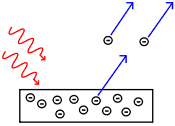
3. Photomultiplier TubesOnly a very small amount of light is given off from the scintillation detector. Therefore, photomultiplier tubes are attached to the back of the crystal. At the face of a photomultipler tube (PMT) is a photocathode which, when stimulated by light photons, ejects electrons. The PMT is an instrument that detects and amplifies the electrons that are produced by the photocathode. For every 7 to 10 photons incident on the photocathode, only one electron is generated. This electron from the cathode is focused on a dynode which absorbs this electron and re-emits many more electrons (usually 6 to 10). These new electrons are focused on the next dynode and the process is repeated over and over in an array of dynodes. At the base of the photomultiplier tube is an anode which attracts the final large cluster of electrons and converts them into an electrical pulse.

Each gamma camera has several photomultiplier tubes arranged in a geometrical array. The typical camera has 37 to 91 PMT’s.

4. Position CircuitryThe position logic circuits immediately follow the photomultiplier tube array and they receive the electrical impulses from the tubes in the summing matrix circuit (SMC). This allows the position circuits to determine where each scintillation event occurred in the detector crystal.

5. Data Analysis ComputerFinally, in order to deal with the incoming projection data and to process it into a readable image of the 3D spatial distribution of activity within the patient, a processing computer is used. The computer may use various different methods to reconstruct an image, such as filtered back projection or iterative reconstruction, both of which are further described in this tutorial.

Leave a Reply
You must be logged in to post a comment.